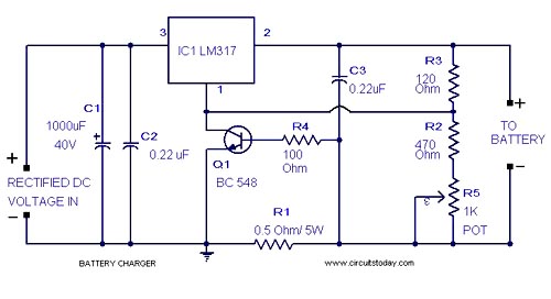
Here is a lead acid battery charger circuit using IC LM 317.The IC here provides the correct charging voltage for the battery.A battery must be charged with 1/10 its Ah value.This charging circuit is designed based on this fact.The charging curent for the battery is controlled by Q1 ,R1,R4 and R5. Potentiometer R5 can be used to set the charging current.As the battery gets charged the the current through R1 increases .This changes the conduction of Q1.Since collector of Q1 is connected to adjust pin of IC LM 317 the voltage at the output of of LM 317 increases.When battery is fully charged charger circuit reduces the charging current and this mode is called trickle charging mode.
Notes .
- Connect a battery to the circuit in series with a ammeter.Now adjust R5 to get the required charging current. Charging current = (1/10)*Ah value of battery.
- Input to the IC must be at least 18V for getting proper charging voltage at the output .Take a look at the data sheet of LM 317 for better understanding.
- Fix LM317 with a heat sink.
"If a maintenance-free lead acid battery could discharge and charge with perfect electrochemical efficiency, there would be no emission of hydrogen or oxygen gas, just the quiet conversion of the plate material, one of lead and the other of lead oxide, both to lead sulfate while the sulfuric acid electrolyte changed to water while discharging; and the reversal of this process during charging.
ReplyDeleteThank you because you have been willing to share information with us. we will always appreciate all you have done here because I know you are very concerned with our. Medical Batteries
ReplyDeleteGreat article with clear insights and practical value. The content is well organised, easy to understand, and helpful for readers looking to learn more about the topic. I really appreciate the useful points, smooth explanation, and professional writing style shared throughout this post.
ReplyDeleteEnrgtech
Panasonic 12V Lead Acid Battery