Sunday, June 29, 2014

Key Chain Light


A key chain with a built-in white LED comes in handy to help you at your front door or search your valuables in the dark. The intensity of white LED is 4000 to 5600 mcd (millicandela) at forward voltage of 3.6V and forward current of 20 mA.


Fig. 1: Circuit for key chain light

Here’s such an LED light circuit for key chains. It comprises a toroidal transformer and two complementary transistors, and is powered by a single AAA cell. Transistors T1 (BC547) and T2 (BC558) form a relaxation oscillator with capacitor C2 (0.01 µF) in the feedback loop. The feedback is controlled by the time constant of timing components R1 and C2, which controls the frequency of operation.
The toroidal transformer steps up the oscillator output to a sufficient value to flash the white LED. The values of R1 and C1 need not be precise. Use of surface mount devices will make the unit more compact.


Fig. 2: Suggested enclosure for key chain light

A single 1.5V AAA cell gives enough brightness. For more brightness, connect two such cells in series. A good-quality white LED from a reputed manufacturer is highly recommended.
Caution. The white LED beam, when viewed directly, can harm the eyes.

Wideband RF Field Strength Meter


Field strength meter is extremely useful when working with RF devices. It can be used to quickly diagnose whether a transmitter circuit is working, and can be used to detect RF signals in the environment. The simplest field strength meter could be built with a tuned LC circuit and a germanium diode, just like the way of a building a crystal radio except replacing the ear piece with a high sensitivity current meter. While this approach fits the needs of most simple applications, it has a pretty narrow frequency range (~100 MHz) and requires tuning the LC circuit to the correct frequency before measurements can be made and the design can become complicated if wider frequency range tuning is desired.

Wideband RF Field Strength Meter

Another option is to use an RF detection chip. Most of such chips (from Linear Technologies, Maxim and Analog Devices) offer a very broad testing range and have much higher sensitivity and accuracy than a simple diode signal detector can offer. Here I will use Linear Technologies’ LT5534 RF detector chip as the field strength meter’s front end. Similar circuits can be build with other RF detection chips as well, depending on the types of the specific application.

LT5534 can detect RF signal from 50MHz all the way up to 3GHz, which covers most of the spectrum one typically uses. If your frequency spectrum is significantly different, you may check out the other RF detection chips the above mentioned companies offer.

The core detector circuit is almost identical to the reference design. The LM324 op-amp forms a differential amplifier with a gain of 2. The main purpose of this differential amplifier is to provide the ability to “zero” the meter reading or adjust the sensitivity of the detector. Since the differential op-amp’s output is proportional to the voltage difference between the output of LT5534 and the wiper voltage of the potential meter, we can adjust the potential meter to set the reference point (i.e. zero reading) for the environment. Also, by raising the wiper’s potential, it would take a higher output from the RF detector for the differential op-amp to register an input voltage and thus effectively lowered the sensitivity of the detector.
The output bandwidth of LT5534 is tens of MHz, since we do not care about the signal details in this particular application, the relatively low bandwidth LM324 has no impact on performance. The above circuit uses a 5V regulated power supply.

Saturday, June 28, 2014

Single transistor Miniature FM transmitter with VCO


This simple transmitter allows you to broadcast on FM radio band (VHF) 87.5 - 108 MHz. It consists of a simple oscillator with silicon planar RF PNP transistor. Directly to the oscillator an antenna is connected. Due to the large amplitude of RF voltage is sufficient antenna length of about 5-10 cm. I used insulated 7cm long copper wire 1mm diameter. I eliminated the tuning capacitor, which is usual for most bugs and miniature transmitters, because this greatly complicates the tuning. From my own experience I know that if you get closer to such capacitor, the operating frequency is changed. That's why I chose to use the voltage tuning using the Voltage Controlled Oscillator (VCO). Instead of tuning capacitor the varicap (capacitance diode) is used, which changes its capacity by changing the reverse DC voltage. We can tune the operating frequency by changing the DC voltage using the trimmer P1. Varicap also provides frequency modulation.

Tuning: Set P1 to the center. Turn on the FM radio and tune it to an unoccupied frequency in the 87.5 - 108 MHz band. You will hear a noise. Turn on the transmitter and the first tune the operating frequency of roughly by stretching turns in the coil L1. Then fine-tune the frequency using P1. Proper tuning is indicated by the radio getting silent. You can then connect audio source to the input (such as cassette player, CD or MP3 player, record player, audio output of PC or laptop, etc.). It is also possible to tune while already connected to the signal source. The circuit can be powered from 5V USB port available on your PC or laptop.


Inductor L1 is airborne and has six turns of 0.5 mm diameter wire wound on 3 mm diameter. Varicap is arbitrary, which covers the range of about 5-20pF, such as BB105, KB105, KB109. I used the varicap KB109G made by Tesla with yellow paint on the cathode. The transistor is a high-frequency planar PNP type, for example, BF970, BF979, or simmilar. You can also use a transistor with different type of case. The disadvantage of the circuit is sensitivy to changes in supply voltage (it is changing the varicap voltage and thus the operating frequency). The antenna is connected directly to the oscillator, so if you touch it or placing it near the conductive object, the frequency shifts. At its simplicity, however, the circuit works surprisingly well and the range is about 20 to 100 meters. You can use power supply of 5-12V or a battery. There should be no ripple in the supply voltage, otherwise it may be heard in the receiver.

     Warning: Broadcasting on VHF-FM band may be illegal in your country. Author does not take any responsibility for your possible legal penalties for illegal broadcast or due to abuse of the bug for illegal purposes! Everything you do at your own risk.


The schematic of the Single transistor Miniature FM transmitter with VCO

88-108 MHz FM covert listening device (bug)


This is a simple listening bug. The signal can be tuned on any FM radio. The first transistor (in the circuit diagram on the left) works as an oscillator (in Colpitts connection), the frequency depends on: trimmer capacitor, inductor (with 4 turns wound on 5mm diameter, no core), varicap and capacitor between collector and emitter of the first transistor. Low frequency signal from the electret microphone affects varicap voltage and thus its capacity. Varicap affectc the oscillator frequency and thus modulates the carrier wave. The second transistor acts as an amplifier and also contributes to separation of the antenna from the oscillator, thereby improving the frequency stability.


How to use the bug: Turn on the FM radio and connect the bug to voltage 9-12 VDC and try to tune the radio frequency bugs. If the bug is near the radio and the radio is well tuned, you can hear feedback whistling. Range of this bug is about 20 to 100m (66 to 330 feet). The antenna is cca 10 - 30cm (1/3 - 1 feet) wire.

  Warning: Broadcasting on VHF-FM band may be illegal in your country. Author does not take any responsibility for your possible legal penalties for illegal broadcast or due to abuse of the bug for illegal purposes! Everything you do at your own risk.

40 Meter QRPp Transmitter


Steve Yates - AA5TB

40m QRPp Transmitter


I built this simple, crystal controlled 40 meter CW transmitter back in 1996. It sports full break-in operation and 250 mW of output power. The final output transistor is a mighty 2N2219A. The N6WG QSL card laying against the lid is just an example of one of the many contacts I have made with this transmitter. The station was located in California and my antenna was an inverted L (bent monopole) operated against a very poor ground system (a couple of ground rods). Considering the losses in my antenna system, I thought the contact was pretty good.

My design was based on one of the late Doug DeMaw's (W1FB) designs with many of my own modifications. The rig is built into an old file box I bought at a garage sale for $1.00.s

Inside View
Inside View

Schematic Diagram

Friday, June 27, 2014

TOUCH_TRIGGERED_BISTABLE


TOUCH_TRIGGERED_BISTABLE
This circuit uses a 555 timer in the bista-ble mode. Touching T2 causes the output to go high; D2 conducts and Dl extinguishes. Touching T1 causes the output to go low; Dl conducts and D2 is cut off. The output from pin 3 can also be used to operate other circuits (e.g., a triac controlled lamp). In this case, the LEDs are useful for finding the touch terminals in the dark. C1 is not absolutely necessary but helps to prevent triggering from spurious pulses.

Wednesday, June 25, 2014

White LED Flood Lamp


This White LED lights illuminates your porch with cool white light. The circuit is too simple and energy saving design. Its current consumption is practically nil but can provide light like a 20 watt CFL lamp. It is directly connected to AC lines to eliminate a bulk transformer

Ultra White LED Lamps are now replacing the fluorescent lamps due to its energy saving property and simplicity of design. White LED emits 1000 to 6000 MCD light and easily works on 3 volts at 20 mA. White LEDs are available as spot light and diffuse type versions. Different sizes like 3mm, 5mm and 10 mm varieties are now common. High watt single white LED is also available. White LEDs was introduced in 1990 which uses Indium Gallium Nitride (InGaN) as the semiconductor. White LED contains a blue chip with white inorganic Phosphor.

When blue light strikes the phosphor, it emits white light. The circuit uses capacitive reactance to drop high volt AC to low volt AC. This reduces power loss due to heat dissipation. The value of the AC capacitor can be calculated using the formulaX c= 1/ (2 π f C)where, Xc is the reactance in ohms, C the capacitance in farads and f the mains frequency.Xc = Vrms / Iwhere Vrms is the input voltage and I is the current flowing through LEDs. The low volt AC (around 100 volts) dropped by C1 is then rectified by a full wave rectifier formed of D1-D4.

Capacitor C2 act as a ripple remover and buffer. Zener diode ZD regulates DC to 69 volts and prevents excess reverse voltage across the LEDs during the negative half cycles.R1 is a must in the circuit to bleed the stored current from C1 when the circuit in unplugged. C1 can store more than 400 volts for many days if R1 is not connected. This can give a lethal shock.

R2 reduces the inrush current.20 LEDs are connected as a string to obtain luminance equal to 20W CFL. Enclose the circuit in a shock proof case. If a reflector is provided behind the LEDs, it will give a flood light appearance.

Important! Do not touch any points or trouble shoot when the circuit is connected to mains.

Caution This is an AC powered circuit and can give fatal shock if handled carelessly. Do not construct the circuit unless you are competent to handle high volt circuits.


Tuesday, June 24, 2014

Bipolar Junction Transistor Beta Tester


Above — Disappointed with the transistor beta testers in our common, low-cost digital multimeters, we did the logical thing; designed and built our own. This collaborative project was more an experiment with BJTs than anything else. It's about as simple a beta measurement device as you can make and still get good results. Preventing damage to our parts inventory underpins this design — the 100 Ω emitter resistor plus ~ 10 microamps of base bias keeps the IC low to help avoid smoke since most new small signal transistors have a beta of 100-400.

Ensure the correct polarity for PNP versus NPN transistors. The voltage divider targets 5 volts using a standard ~12 volt supply; I just used whatever resistors were handy and ended up with the 6K8 — 3K3 pair. VCC should be regulated. Perform the measurements with a single multimeter allowing time for stabilization.

To use: Set the potentiometer so that the voltage drop across the 10K resistor is 100 mV. Then move your DMM leads to the 100 Ω resistor and measure the beta. This device measures beta, the static gain at DC.

Measuring beta is a bit inexact since beta is affected by so many variables as follows:

  1. Beta tends to be low at low operating currents and rises and plateaus for medium currents and then falls at higher currents.
  2. Beta tends to increase with temperature.
  3. Beta is affected by the voltage between the collector and emitter -- this is a weak effect except when the voltage is very small.
  4. The beta can vary as the battery depletes in DMM beta testers.

Saturday, June 21, 2014

Simple Crystal Tester


Here is a simple circuit that can be used to test a crystal before using it in a circuit. The circuit is built around two BC547 transistors (T1 and T2) and a few discrete components.
The oscillator circuit formed by transistor T1, resistors R1 and R2, and capacitors C1 and C2 oscillates if a good crystal is connected to the test points marked as CUT (crystal under test). The output from the oscillator is rectified by diode D1 and filtered by capacitor C3. The positive voltage appearing across the capacitor is fed to the base of transistor T2, causing it to conduct.

Testing of a crystal is simple: Insert the crystal at CUT points shown in the circuit diagram and press test switch S1. If LED1 glows, your crystal is good and you can use it in a circuit.The circuit is powered by a standard 9V battery. Push-to-on switch S1 is included to prolong the battery life but it’s not needed if you use a socket for the crystal under test.Assemble the circuit on a general-purpose PCB and enclose in a suitable small cabinet. Fix the two-pin connector, LED1 and test switch on top of the cabinet. Fix the 9V battery inside the cabinet.

Crystal AM Transmitter


Here is the circuit of a medium-power AM transmitter that delivers 100-150 mW of radio frequency (RF) power. At the heart of the circuit is a crystal oscillator. A 10MHz crystal is used to generate highly stable carrier frequency. Audio signal from the condenser mic is amplified by the amplifier built around transistors T1, T2 and T3. The amplified audio signal modulates the RF carrier generated by the crystal oscillator built around transistor T4. Here modulation is done via the power supply line. The amplitude-modulated (AM) signal is obtained at the collector of oscillator transistor T4.


Fig. 1: Circuit of crystal AM transmitter


Fig. 2: Oscillator coil


Fig. 3: Modulation transformer

By using matching dipole antenna and co-axial cable, the range of signal transmission can be increased. For maximum range, use a sensitive radio with external wire antenna. The circuit works off a 9V-12V battery. For oscillator coil L1, wind 14 turns of 30SWG wire round an 8mm diameter radio oscillator coil former with a ferrite bead (see Fig. 2). For modulation transformer X1, you can use the audio output transformer of your old transistor radio set. Alternatively, you can make it from E/I section transformer lamination with inner winding having 40 turns of 26SWG wire and the outer winding having 200 turns of 30SWG as shown in Fig 3.

LONG RANGE SHORT WAVE TRANSMITTER


This transmitter circuit operates in shortwave HF band (6 MHz to15 MHz), and can be used for shortrange communication and for educational purposes.

The circuit consists of a mic amplifier, a variable frequency oscillator, and modulation amplifier stages. Transistor T1 (BF195) is used as a simple RF oscillator. Resistors R6 and R7 determine base bias, while resistor R9 is used for stability. Feedback is provided by 150pF capacitor C11 to sustain oscillations. The primary of shortwave oscillator coil and variable condenser VC1 (365pF, 1/2J gang) form the frequency determining network.

By varying the coil inductance or the  capacitance of gang condenser, the frequency of oscillation can be changed. The carrier RF signal from the oscillator is inductively coupled through the secondary of transformer X1 to the next RF amplifier-cum-modulation stage built around transistor T2 that is operated in class ‘A’ mode. Audio signal from the audio amplifier built around IC BEL1895 is coupled to the emitter of transistor 2N2222 (T2) for RF modulation.

IC BEL1895 is a monolithic audio power amplifier designed for sensitive AM radio applications. It can deliver 1W power to 4 ohms at 9V power supply, with low distortion and noise characteristics. Sincen the amplifier’s voltage gain is of the order of 600, the signal from condenser mic can be directly connected to its input without any amplification.

The transmitter’s stability is governed by the quality of the tuned circuit components as well as the degree of regulation of the supply voltage. A 9V regulated power supply is required. RF output to the aerial contains harmonics, because transistor T2 doesn’t have tuned coil in its collector circuit. However, for short-range communication, this does not create any problem.The harmonic content of the output may be reduced by means of a high-Q L-C filter or resonant L-C traps tuned to each of the prominent harmonics. The power output of this transmitter is about 100 milliwatts.

VHF FM Transmitter MAX2606


VHF FM Transmitter MAX2606

If you want to be independent of the local radio stations for testing VHF receivers, you need a frequency-modulated oscillator that covers the range of 89.5 to 108 MHz — but building such an oscillator using discrete components is not that easy. Maxim now has available a series of five integrated oscillator building blocks in the MAX260x series which cover the frequency range between 45 and 650 MHz. The only other thing you need is a suitable external coil, dimensioned for the midrange frequency.

Phone Spy Transmitter


Phone Spy Transmitter

Here is a very simple telephone broadcaster transmitter which can be used to eavesdrop on a telephone conversation. The circuit can also be used as a wireless telephone amplifier. One important feature of this phone transmitter is that the circuit derives its power directly from the active telephone lines, and thus avoids use of any external battery or other power supplies.

1.5V FM Transmitter


1.5V FM Broadcast Transmitter

The objective of this 1.5V FM Broadcast Transmitter design is to provide a simple low-power transmitter solution for broadcasting audio from various audio sources. This transmitter accepts stereo input via two 470K resistors. Since there is no audio level control on the input, the audio level out from the source needs to be adjusted. Or, you can just add a 10k as an input level control. Transmitter's frequency, as built is tunable via spreading or compressing the coil to the desired frequency, and the coil can be glued down. If you want to make one that's tunable, it might be easiest to reduce the 18 pf capacitor and put a small trimmer capacitor in parallel with the inductor (across the reduced value capacitor). Voltage variable capacitors would be an nice alternative to a mechanical variable capacitor but they don't offer much tuning range with only a 1.5V power supply.

Coil less FM Transmitter


Coilless FM Transmitter

The RF oscillator using the inverter N2 and 10.7Mhz ceramic filter is driving the parallel combination of N4 to N6 through N3.Since these inverters are in parallel the output impedance will be low so that it can directly drive an aerial of 1/4th wavelength. Since the output of N4-N6 is square wave there will be a lot of harmonics in it. The 9th harmonics of 10.7Mhz (96.3Mhz) will hence be at the center of the FM band. N1 is working as an audio amplifier. The audio signals from the microphone are amplified and fed to the varicap diode. The signal varies the capacitance of the varicap and hence varies the oscillator frequency which produce Frequency Modulation.

4 Transistor FM Transmitter


4 Transistor FM Transmitter

This circuit provides an FM modulated signal with an output power of around 500mW. The input microphone pre-amp is built around a couple of 2N3904 transistors (Q1/Q2), and audio gain is limited by the 5k preset trim potentiometer. The oscillator is a colpitt stage, frequency of oscillation governed by the tank circuit made from two 5pF ceramic capacitors and the L2 inductor. The output stage operates as a 'Class D' amplifier, no direct bias is applied but the RF signal developed across the 3.9uH inductor is sufficient to drive this stage. The emitter resistor and 1k base resistor prevent instability and thermal runaway in this stage.

RF Filter


rf filter

Crystal Tester


xtal tester

AM Rebroadcaster

rebroadcaster

AM Modulation Monitor

modulation meter

FM Wireless Transmitter


fm mike

Field Strength meter

field meter

CB Sniffer probe


cb sniffer

Cheap BFO for SWLs

bfo

Friday, June 20, 2014

Small AM transmitter


This unit is an AM transmitter assembled in a small tin box. It is designed to connect to the audio amplifier. On the right, the power switch and antenna wire can be seen. The transmitter is tunable from 1500 to 2000 KC.

Although it works as designed, it is effective only with a long antenna wire, or a very sensitive receiver. Note the two 3.3K resistors - if one is jumpered, then the power output is reduced. The 2N43 directly modulates the RF oscillator, so there is likely some FM component introduced as well.

Pixie2 QRPp AM Transmitter


The Pixie2 is a simple QRP CW transmitter that dozens of ham radio operators have successfully built. (QRP is ham jargon for low-power operations, and CW is the simplest method of sending Morse code merely by turning a carrier-wave on and off.) The Pixie2 is usually built for the 40 meter band but it will work on frequencies from 1000 kHz up to at least 15 MHz. It is said to output a couple hundred milliwatts of RF.

The circuit can be amplitude modulated quite easily. A small audio amplifier feeds audio current into the 8-ohm side of a transformer. The 1k ohm side of the transformer is inserted in the V+ supply going to the Pixie's output transistor.

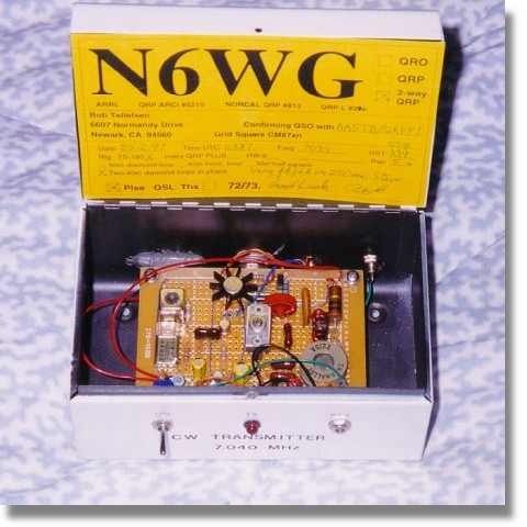
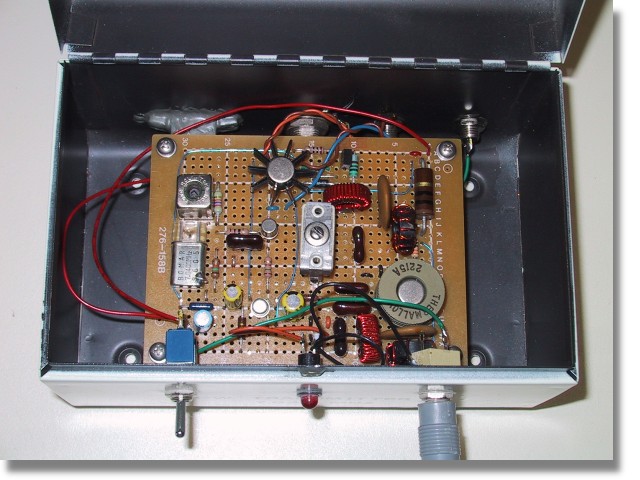
This modified Pixie2 is called the Talking Pixie. It has 18 components (not counting circuit board, jacks, power supply and external audio amp). Building it on a prototyping board only takes a few minutes if all the parts are available.

schematic

The level of the audio fed to the transformer is adjusted until the best sound quality is achieved. The Talking Pixie will not sound as loud as commercial stations but the user must avoid the temptation to over-modulate; nobody will listen to an over-modulated signal.

parts list

C1: 100 pF
C2: 220 pF
C3: 82 pF
C4: .01
C5: .01
L1: 150 uH
L2: 22 uH
Q1: 2N2222 or 2N3904
Q2: 2N2222A (metal can type) or 2N3866
R1: 47K
R2: 1200
R3: 33K
R4: 10 or 15 ohms (experiment!)
T1: 1000 ohm to 8 ohm audio transformer

The frequency is crystal-controlled. A crystal for the frequency you're interested in will have to be ordered if you don't have one handy.

The transformer must be rated to handle at least half a watt of audio; a very tiny transformer will not sound good and will have too much resistance on the 1K winding.

L3, C6 and C7 form a low-pass filter to attenuate the harmonics generated by the circuit. Specific values for various frequencies can be found on the Medium Wave Alliance's filters page.

L1 and L2 are factory-made axial molded chokes.

variations

The impedance and bandwidth of the antenna will affect the sound quality of AM transmitters like the Talking Pixie. What sounds good on the test bench with a 50-ohm dummy load attached to the output might not sound as good with real-world antennas like short end-fed wires. Some kind of antenna tuner might be helpful. (By the way, two 100-ohm resistors in parallel make an adequate dummy load for this rig.) Needless to say the size and efficiency of the antenna will have a major impact on the range.

photo

If you build the circuit on a prototyping board (as shown above), you can experiment with many variations on the circuit design.

Here are some modifications that have been suggested...

Martin Spencer suggested using a FET (such as 2N7000) instead of an NPN transistor for Q2. This could give more linear modulation. Replace L1 with a 5K variable resistor; remove the crystal for a moment and adjust the resistance for about 2 mA drain current.

Mark Weiss wrote: "You can put another transistor in series with the PA and use it as a series voltage source. By varying this voltage control element with the audio signal, highly linear modulation is achieved. Transformers tend to present variable impedances, causing the PA to be less stable under varying load conditions. A direct-coupled modulator can offer the potential for great tolerance of loads that aren't precisely +50 j0."

Other QRP CW transmitters can also be modified for amplitude modulation. You will find schematicsfor such transmitters in ham radio books and magazines, and on websites operated by QRP clubs.

Hobby AM Transmitter


Here is the circuit diagram of a simple AM transmitter circuit that can transmit your audios to your backyard.This circuit is designed with limited  power output to match the FCC regulations and still produces enough amplitude modulation of voice in the medium wave band to satisfy your personal needs.You will love this!.

The circuit has two parts , an audio amplifier and a radio frequency oscillator. The oscillator is built around Q1 (BC109) and related components. The tank circuit with inductance L1 and capacitance VC1 is tunable in the range of 500kHz to 1600KHz. These components can be easily obtained from your old medium wave radio. Q1 is provided with regenerative feedback by connecting the base and collector of Q1 to opposite ends of the tank circuit. C2 ,the 1nF capacitance , couples signals from the base to the top of L1, and C4 the 100pF capacitance ensures that the oscillation is transfered from collector, to the emitter, and through the internal base emitter resistance of the transistor Q2 (BC 109) , back to the base again. The resistor R7 has a vital part in this circuit. It ensures that the oscillation will not be shunted to ground trough the very low value internal emitter resistance, re of Q1(BC 109), and also increases the input impedance such that the modulation signal will not be shunted to ground. Q2 is wired as a common emitter RF amplifier, C5 decouples the emitter resistance and unleashes full gain of this stage. The microphone can be electret condenser microphone and the amount of AM modulation can be adjusted by the 4.7 K variable resistanceR5.

Am Transmitter Circuit Diagram with Parts List.

Am Transmitter Circuit

Am Transmitter Circuit Diagram

Notes .
  • The transmission frequency can be adjusted using the variable capacitance C3.
  • Use a 200uH inductor for the L1 in the tank circuit.
  • Power the circuit using a 9V battery for noise free operation.
  • Use a 30 cm long insulated Copper wire as the antenna.

Thursday, June 19, 2014

Transmitter Circuits Collection


TOBACCO TIN TRANSMITTER


I would like to show you my novelty transmitter project which I have enclosed into a tobacco tin. It requires very few parts, they are very easy to obtain, most of them came from my junk box with the exception of the crystal (7.030 MHz) which is an international QRP calling frequency. Any crystal will do as long as the operating frequency is within the amateur band, preferably in the CW section.

CIRCUIT

This is a one transistor crystal controlled transmitter, it uses the 2N2222 transistor in a basic oscillator arrangement, and has a simple output filter section for any unwanted harmonics. If the output filter was not used  the transmitted frequency would not only be 7.030 MHz but also 14.060 and 28.120 MHz etc. These unwanted frequencies are called harmonics. The output power is only 250 milliwatts (quarter of a watt) but high harmonic output is illegal even at this low power.  

CONSTRUCTION

I have used the ugly style construction, this is where you start with an off cut of copper clad board material, and build the circuit on the copper side up. The copper surface makes a low impedance ground and a anchor point for components. The grounded or copper surfaced components make a good solid support for the rest of the circuit to be built on. It is up to you as the builder which style you use, but the ugly construction is a lot cheaper than buying expensive vero board or making a printed circuit board. As you can see from the diagram there are very few parts, and it is straight forward to build. RFC1 is 6 turns of 32 s.w.g. enameled copper wire wound on a tiny ferrite bead, any thin wire and ferrite bead should work. The toroid in the output filter section is 14 turns of 26 s.w.g enameled copper wire wound around a T50-2 core.

OPERATING

When you have finished just press your morse key, no tune up procedure is necessary. You will also need an HF receiver, or shortwave radio with a BFO to operate with, I use a Realistic DX-394 receiver with an indoor wire and the transmitter next to the receiver with any of my outdoor antennas, but you could operate both from one antenna with a changeover switch. Although the transmitter only has 250 miliwatts this circuit when connected to a good outdoor antenna such as a dipole in favorable conditions has worked DX over 7000 miles. You will notice I have left a space on the right hand side of the box, this is to put an optional PP3 9 volt battery inside if I am going portable.

OTHER BANDS

The transmitter can also be  built to work on 80, 30 and 20 meters with the crystal of your choice, and the following changes=

80 meters =T50-2 toroid 21 turns capacitors 1, 2 and 3 =750 pfd

30 meters = T50-2 toroid 13 turns capacitors 1,2 and 3 =330pfd

20 meters =T50-2 toroid 12 turns capacitors  1, 2 and 3=270pfd

Please note It is illegal to operate this transmitter without an hf license.

Happy building and good DX M0DAD.

http://users.whsmithnet.co.uk/m0dad/construcion/tobacco_tin_transmitter.htm