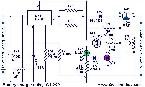
A very simple battery charger circuit having reverse polarity indication is shown here.The circuit is based on IC L200 . L200 is a five pin variable voltage voltage regulator IC.The charging circuit can be fed by the DC voltage from a bridge rectifier or center tapped rectifier.Here the IC L200 keeps the charging voltage constant.The charging current is controlled by the parallel combination of the resistors R2 & R3.The POT P1 can be used to adjust the charging current.This circuit is designed to charge a 12 V lead acid battery.The transistor t1,diode D3 and LED are used to make a battery reverse indicator.In case the battery is connected in reverse polarity ,the reverse polarity indicator red LED D5 glows.When the charging process is going on the battery charging indicator green LED D4 glows.
Circuit diagram with Parts list.
Notes.
- The circuit can be assembled on a good quality PCB or common board.
- The values of R2 & R3 can be obtained from the equation,
(R2//R3) =( V5-2)/(Io).
Where V5 is the charging voltage (voltage at pin 5) and Io is the charging current.
- The POT R8 can be used for fine adjustments of charging current.
- If battery is connected in reverse polarity the RED LED will glow.
- When the charging is going on the GREEN LED will glow.
- The rectified input voltage to the charger can be 18V.
Cool Electronics Circuits: Battery Charger Circuit Using L200. >>>>> Download Now
ReplyDelete>>>>> Download Full
Cool Electronics Circuits: Battery Charger Circuit Using L200. >>>>> Download LINK
>>>>> Download Now
Cool Electronics Circuits: Battery Charger Circuit Using L200. >>>>> Download Full
>>>>> Download LINK