Tuesday, May 17, 2011

LASER Transmitter and Receiver

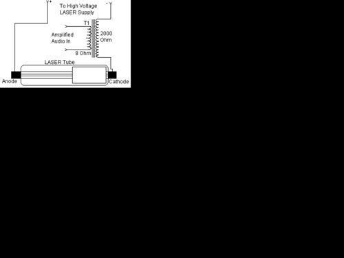
This set of two circuits from the basis for a very simple light wave transmitter. A LASER beam is modulated and then aimed at a receiver that demodulates the signal and then presents the information voice, data, etc.. The whole thing is very easy to build and requires no specialized parts execpt for the LASER itself.
Part Total Qty. Description Substitutions

C1, C2 2 0.1uf Ceramic Disc Capacitor
C3 1 100uf 25V Electrolytic Capacitor
R1 1 100K Ohm 1/4W Resistor
R2 1 1M Ohm 1/4W Resistor
R3 1 10K Pot
Q1 1 NPN Phototransistor
U1 1 741 Op Amp
U2 1 LM386 Audio Amp
SPKR1 1 8 Ohm Speaker
T1 1 8 Ohm:2K Audio Transformer
MISC 1 Wire, Board, Knob For R3, LASER Tube and Power Supply

LASER Transmitter and Receiver

Build a Wi-Fi antenna using household materials


Who'd have thought that a toilet-brush holder, of all things, would turn out to be an excellent Wi-Fi antenna? The lesson is that you can achieve great results for little expense - and half an hour's work.The range of a WiFi router can be considerably extended simply by connecting a directional antenna. Standard omni-directional stub antennas are at the lower end of the performance scale, and they quickly come up against their limits when you need to give your own home better coverage, provide your neighbour with DSL, or pick up as many radio networks as possible while war driving.If the access point is three rooms further on, or even in the house on the other side of the road, you need a directional antenna. If you have to make a connection to your nearest DSL-equipped acquaintance at the other end of the village street, or to bridge even longer radio links to reach the free radio[1] node in the next block but one, you may even require two directional antennas.

Neighbourhood WiFi routers with omni-directional aerials are in any case the worst sources of interference in a city. A single block of flats can easily contain over ten wireless networks, all chattering away simultaneously. Mutual interference is inevitable, with the result that range and connection stability are drastically reduced.Replacing just one of two antennas at the base station can be a way of improving WiFi coverage, for example, down to the bottom of the garden. The near zone is served by the remaining stub. All current WiFi modules automatically use the most suitable antenna for each client, a process called antenna diversity. Even with models having only one external antenna, it's worth having a look inside the casing. Usually, a tiny socket for the second antenna is fitted on the WiFi module. Depending on the manufacturer, this type of plug is called U.FL or Ipex. The connection can easily be led out through a ventilation slot with a short adaptor cable ("pigtail"). On some WiFi notebook cards and USB sticks, there is also an antenna plug, and a look at the data sheet will tell you its type – normally SMA or RPSMA.

The simply made tin-can antenna, with the dimensions given here, is suitable for base stations and for clients who transmit on 2.4 GHz in accordance with the IEEE 802.11b and 802.11g standards. 802.11a uses the 5-GHz band, requiring different antenna dimensions. The necessary background for a recalculation is given in an article on building tin-can radio antenna (Building a Wi-Fi Antenna Out of a Tin Can) [2]

Very recent base stations that comply with the draft standard 802.11n also use the 2.4 GHz band. But they automatically use a number of methods to combine their antennas for optimal range and speed. However, this only works if the antennas have the characteristics expected by the WiFi chipset.


http://www.h-online.com/features/Build-a-Wi-Fi-radio-relay-using-household-materials-747382.html?view=print
Ham Radio BFO


Ham Radio (amateur radio) is a popular hobby amongst electronics enthusiasts all over the world. Basically the hobby involves a person in making his own gear consisting of a receiver and transmitter or a transceiver (a receiver and a transmitter in one unit) after procuring a licence from the Ministry of Communications. Home brewing or self construction, an integral part of the hobby, has been sadly neglected in our country, despite the fact that various institutions with governmental help have come into being recently.

Hams aboard can buy the latest transceiver off the shelf at a reasonable price and go on the air immediately. But in India, with a sixty per cent duty involved (now changed?), a commercial transceiver would cost a whopping Rs: 50,000. Hence, it is beyond the reach of an average Indian Ham.

The Indian ham is often handicapped for want of ham gear. To overcome this shortcoming a small receiver and a transmitter can be home brewed with indigenously available components. The total outlay may not exceed a few hundred rupees. Some of you may wonder if this is feasible with out fancy test equipment like oscilloscopes and LC bridges etc. Yes it is possible.

Everything-that-moves ALARM Project

A crucial failing of proximity detectors is their unreliable and tricky nature. This is where they are used to detect humans, not to speak of smaller living beings. One common approach is to detect eddy currents in a living body, which are induced in the body through a.c. mains wiring. However, such circuits become altogether unusable in the case of mains failure, or in the absence of mains electricity, or even where adjacent mains circuits are switched in and out.

https://blogger.googleusercontent.com/img/b/R29vZ2xl/AVvXsEgXt2avH29wkE9Ppp0HxBFp9T5zQ3VT-4j4vT_8vnvUeBYrF7pAHEO_RE2sn-YQ0cNRGibcqBHWJRaGmrxYgdjuVW9p49BbK41lgoRfRjLYpC-vaBxdgAMlEoiOtmtbbgIm7SIU51PIf6Kq/s1600/everything_that_moves_alarm.gif
The circuit of Fig.1 takes the guesswork out of proximity detection by inducing eddy currents in a living being, whether animal or human. Five turns of enamelled copper wire (say 30 s.w.g.) are wound around the area within which detection is to take place (4m x 4m in tests), and an audio signal of about ¼ Watt is pulsed through this, the Tx, coil. A smaller Rx coil (say 100 turns of 30 s.w.g. enamelled copper wire wound on a 150mm dia. former) is used as a pick-up coil. The circuit is adjusted by means of tune and fine-tune controls VR1 and VR2, so that it is deactivated when one stands back from the Rx coil.A simple clock generator (IC1a-IC1b) and power MOSFET (TR1) are used for the transmitter, and a 7555 timer (IC2) is wired as a sine-square convertor for the receiver. IC2's inputs are biased through VR1, VR2 and R4. IC2 in turn switches NAND gates IC1c and IC1d, to drive relay RLA. Capacitor C5 switches the relay for about two seconds, and its value may be increased or decreased to give different timing periods. D2 is critical to prevent back-e.m.f. from re-triggering the circuit. Supply decoupling capacitors C1 and C4 are also critical, and should be located close to IC1 and IC2 respectively.

When a living being - animal or human - comes within tens of centimetres of the Rx coil, the circuit is triggered. This coil may be placed in the threshold of a door, under a carpet, or around a hatch, at the base of a tree, and so on. A number of such coils may also be wired in series.Coils may be wound with a larger or smaller diameter, with more or less turns, and the power of the transmitter may be varied, as well as the sensitivity of the receiver. Note that a.m. radio reception may be affected at close proximity to the Tx coil.


author: Thomas Scarborough
web site: http://www.electronics-lab.com

Make a Transistor at Home


In a MAKE: magazine video, Jeri shows how to make a point contact transistor with germanium and phosphor bronze contacts.
Watch - Make a Point Contact Transistor at home...


http://www.southgatearc.org/news/november2010/make_a_transistor.htm

Saturday, May 14, 2011

W1FB 6M RF Preamp

image


Here is a schematic sent to me by W1FB many years ago. It is very similar to a 6M two-stage preamp that he published in QST in the mid eighties. Doug really favored the grounded gate FET for narrow band preamps. His published work is replete with examples of them on just about every band. I built that amp and remember getting about 10 dB gain, which is all that I wanted for the 6M direct conversion receiver using a diode ring detector that I was building. The great feature of the amp is that it combines a band pass filter and preamp in one. I lost the original schematic that Doug sent me but was delighted to see that I made a bitmapped drawing of it on a floppy disk that was recently re-discovered when we were moving an old desk. The shield shown in the schematic was a small piece of grounded ,double sided PC board in which, I made a small chamfered hole in to pass the lead going to the T2 tap. The shield, along with very short component leads will help minimize parasitic oscillations. The T2 tap is 3 turns down from the end of the T2 main winding that connects to the variable capacitor. Doug specified T37-10 cores for the inductors, but I substituted T37-6 cores and used the same number of windings as specified for the T37-10 core inductors. It worked fine.


http://www.qrp.pops.net/preamp.asp

How to make foxhole radio receiver (with no batteries)


Foxhole radio receiver or Crystal receiver is a form of radio that does not operate on local oscillator, which makes it hard to be detected by other electronic device. One of the most interesting thing of Foxhole radio is that it could be operated without the use of batteries, as it is powered solely by the radio waves through its long wire antenna.

Foxhole radio was (supposedly) popular during World War II because it enabled the GI to receive radio broadcast in the middle of the war, particularly in France as the Germans has outlawed the use of radio by civilians, thus the American GI need to build their own receiver to receive broadcasts. Typical component of foxhole radio during those days are : a period razor blade (not the newer galvanized one), carbon (obtained from pencil) and some copper wire with woodblock or cardboard as its base.


http://please.name.my/302/how-to-make-foxhole-radio-receiver-with-no-batteries.html