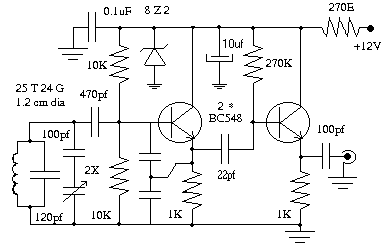
Variable frequency oscillator uses two numbers of BC548. For 40 meter band VFO oscillates form 2.567 MHz to 2.667 MHz which on mixing with 4.43 MHz generates 7.0 MHz to 7.1 MHz. If you have a frequency meter it is easy to calibrate the VFO, otherwise connect a 2J gang condenser in parallel with VFO coil and adjust it to receive ham stations. VFO is fixed inside a small aluminum box.
Tuesday, February 22, 2011
24V Battery Chargers
For those of you who are looking for battery charger circuit, here is some reference circuit 24V battery charger for lead acid. The 24v charger is using several variable voltage regulator IC such as LM350K and LM317K.
For those who want to create 24V battery charger with high current, it is advisable to use as a source of DC voltage transformers. Because quite easy to arouse the current, just based on how the capacity of the transformer you have.
All 24V battery chargers below is intended to 24V charging voltage, the difference in the composition of the batteries if made series or parallel. Some of the following 24Vbattery charger collected from various sources from the internet, making it more feasible to use as a technical reference as comparative material to create a new 24V battery charger for personal or limited use.
24V Battery Charger Circuit 47 AH
This is a 24V battery charger for lead acid that uses a LM317 variable voltage regulator. Charging current of charger is set at 700 mA, determined by the value of the 10K potentiometer resistance. Charging voltage is determined by the value resistor 100 ohm and 0.82 (0.85) ohm. Diode D1 prevents reverse flow of current from the battery when the charger is switched OFF or when electrical power is not available.
24V Battery Charger Circuit
No parameters are important in this 24V battery charger, unless the design that assumes each 12V battery contains 6 cells. When two batteries are connected in series, voltage and will increase the existing capacity remains the same.
24V Battery Charger/Backup – Dual Mode
24V Battery Charger/Backup-Dual Mode
This 24V battery charger for lead acid using variable voltage regulators LM350K. This 24v charger also serves as a backup voltage sourced from the battery itself. Filling done in series on two 12V cells.
24V Battery Charger Circuit
Li-ion Battery Charger for Mobile phone by TL431
This is a simple to build charger for single 3.7V lipo battery. The heart of the charger is TL431 shunt regulator that controls the incoming current. Charger comes with a convenient charging LED indicator. As charging current goes down so does the intensity of the LED.
Lead acid battery charger circuit
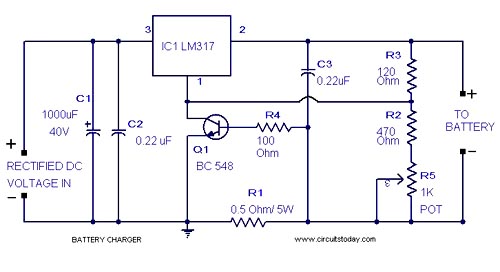
Here is a lead acid battery charger circuit using IC LM 317.The IC here provides the correct charging voltage for the battery.A battery must be charged with 1/10 its Ah value.This charging circuit is designed based on this fact.The charging curent for the battery is controlled by Q1 ,R1,R4 and R5. Potentiometer R5 can be used to set the charging current.As the battery gets charged the the current through R1 increases .This changes the conduction of Q1.Since collector of Q1 is connected to adjust pin of IC LM 317 the voltage at the output of of LM 317 increases.When battery is fully charged charger circuit reduces the charging current and this mode is called trickle charging mode.
Notes .
- Connect a battery to the circuit in series with a ammeter.Now adjust R5 to get the required charging current. Charging current = (1/10)*Ah value of battery.
- Input to the IC must be at least 18V for getting proper charging voltage at the output .Take a look at the data sheet of LM 317 for better understanding.
- Fix LM317 with a heat sink.
USB-Powered Lithium-Ion Battery Charger by LM3622
The battery-charger circuit is designed to operate as a high power USB function. To be compliant with USB Specifications (Rev. 1.1), a high-power function must not draw more than 500 mA from the bus during normal operation. The LM3622 uses the 0.25 current-limit resistor R1 to set a 400 mA maximum charging current. This leaves a 100 mA surplus that can be used to supply USB control circuitry and other functions in the device.
There are additional current restraints on a high-power USB function that apply during system start-up or when a device is initially connected to an active bus. Until a device is properly configured by the USB system, the device may not draw more than 100 mA from the bus. In the above design, National Semiconductor s LM3525 USB power switch keeps the battery charger circuit isolated from the bus during start-up so that the charge current does not overload the bus. When the port is properly enumerated, a USB control signal enables the LM3525 switch, connecting USB power (VBUS) to the charger circuit. In addition to on-and-off switching, the LM3525 provides over-current and under-voltage protection to the design.
Read More Source:http://www.national.com/nationaledge/feb01/usb.html
Thank you.
Monday, February 21, 2011
NiCd BATTERY CHARGER
This NiCd battery charger can charge up to 8 NiCd cells connected in series. This number can be increased if the power supply is increased by 1.65v for each additional cell. If the BD679 is mounted on a good heatsink, the input voltage can be increased to a maximum of 25v. The circuit does not discharge the battery if the charger is disconnected from the power supply.
Usually NiCd cells must be charged at the 14 hour rate. This is a charging current of 10% of the capacity of the cell for 14 hours. This applies to a nearly flat cell. For example, a 600 mAh cell is charged at 60mA for 14 hours. If the charging current is too high it will damage the cell. The level of charging current is controlled by the 1k pot from 0mA to 600mA. The BC557 is turned on when NiCd cells are connected with the right polarity. If you cannot obtain a BD679, replace it with any NPN medium power Darlington transistor having a minimum voltage of 30v and a current capability of 2A. By lowering the value of the 1 ohm resistor to 0.5 ohm, the maximum output current can be increased to 1A.
White Led driver
The circuit below can be modified to drive up to 30 white LEDs. The effectiveness of a LED array increases when they are spread out slightly and this makes them more efficient than a single 1 watt or 2 watt LED. The two modifications to the circuit make the BC337 work harder and this is the limit of the inductor. The current consumption is about 95mA. The winding details for the transformer are shown above.
H-BRIDGE PUSH-PULL DOG-BARK STOPPER
The two circuits above are also H-Bridge Push-Pull outputs, however the current is limited to 200mA or less. In this design the current can be 3 amps or more, depending on the supply voltage, the resistance of the load and the type of driver transistors. About 2v5 is lost between "c and e" due to the output of the 555 and the base-emitter voltage of the driver transistors. This circuit drives an ultrasonic transducer (speaker) at 20kHz to 40kHz to subdue dog barking. If the unit is turned on by remote control every time the dog barks, the animal will soon learn to cease barking.
TV REMOTE CONTROL JAMMER
This circuit confuses the infra-red receiver in a TV. It produces a constant signal that interferes with the signal from a remote control and prevents the TV detecting a channel-change or any other command. This allows you to watch your own program without anyone changing the channel !! The circuit is adjusted to produce a 38kHz signal. The IR diode is called an Infra-red transmitting Diode or IR emitter diode to distinguish it from a receiving diode, called an IR receiver or IR receiving diode. (A Photo diode is a receiving diode). There are so many IR emitters that we cannot put a generic number on the circuit to represent the type of diode. Some types include: CY85G, LD271, CQY37N(45¢), INF3850, INF3880, INF3940 (30¢). The current through the IR LED is limited to 100mA by the inclusion of the two 1N4148 diodes, as these form a constant-current arrangement when combined with the transistor and 5R6 resistor.
TRAFFIC LIGHTS
Here's a clever circuit using two 555's to produce a set of traffic lights for a model layout.
The animation shows the lighting sequence and this follows the Australian-standard. The red LED has an equal on-off period and when it is off, the first 555 delivers power to the second 555. This illuminates the Green LED and then the second 555 changes state to turn off the Green LED and turn on the Orange LED for a short period of time before the first 555 changes state to turn off the second 555 and turn on the red LED. A supply voltage of 9v to 12v is needed because the second 555 receives a supply of about 2v less than rail. This circuit also shows how to connect LEDs high and low to a 555 and also turn off the 555 by controlling the supply to pin 8. Connecting the LEDs high and low to pin 3 will not work and since pin 7 is in phase with pin 3, it can be used to advantage in this design.
MOSQUITO REPELLER
This circuit produces a tone above the human audible range and this is supposed to keep the mosquitoes away. You need a piezo diaphragm that will respond to 15kHz and these are very difficult to find.
170v SUPPLY FOR NIXIE TUBES
This circuit produces approx 170v for Nixie tubes and other neon tubes. It is a switch-mode boost circuit.
12v to 240v INVERTER
This circuit will produce 240v at 50Hz. The wattage will depend on the driver transistors and transformer.
ZENER DIODE TESTER
This circuit will test zener diodes up to 56v. See Talking Electronics website, left index, 200 Transistor Circuits (circuits 1-100) and go to Zener Diode (making) to see how to make a zener diode and how to create a zener voltage from a combination of zeners. Place the zener across the terminals in the circuit below and read the value across it with a multimeter set to 50v range.
TRANSISTOR TESTER
The 555 operates at 2Hz. Output pin 3 drives the circuit with a positive then zero voltage. The other end of the circuit is connected to a voltage divider with the mid-point at approx 4.5v. This allows the red and green LEDs to alternately flash when no transistor is connected to the tester.If a good transistor is connected, it will produce a short across the LED pair when the voltage is in one direction and only one LED will flash. If the transistor is open, both LED’s will flash and if the transistor is shorted, neither LED will flash.
SERVO TESTER
This circuit can be used to manually turn a servo clockwise and anti-clockwise. By pushing the forward or reverse button for a short period of time you can control the rotation of the servo. It will also test a servo. Here is a photo of a kit from Cana Kit for $10.00 plus postage (it is a slightly different circuit) and a motor and gearbox, commonly called a "servo." The output shaft has a disk or wheel containing holes. A linkage or push-rod is fitted to a hole and when the disk rotates, the shaft is pushed and pulled. The shaft only rotates about 180° to actuate flaps or ailerons etc.
A pot can be used to control the position of the servo by using the following circuit. It produces a positive pulse between about 0.9 milliseconds and 2.1 milliseconds. The off period between pulses is about 40 milliseconds. This can be shortened by reducing the value of the 3M3 resistor.
CAR TACHOMETER
A 555 is configured as a monostable or one shot in this project. The period of the 555 is determined by the 47k and the capacitor from pin 6 to ground (100n). Time "T" = 1.1 RC or 1.1 X 50,000 X 0.1 X10 -6 = 0.0055 or 5.5 mS (milli-seconds). The 555 receives trigger pulses from the distributor points. These are limited by the 1k and 5v zener diode. These are AC coupled to the trigger input through the 100n coupling capacitor. The 50mA meter receives pulses of current through the 200k pot to show a reading.
Integration of the current pulses produces a visible indication of the cars engine speed on the 0-1mA meter.Supply is taken from the cars 12v system and for the 555 it is reduced to a regulated 9v by the 15 ohm resistor in conjunction with the 9v zener diode. Note: the 10u electrolytic must be placed physically as close as possible to supply pin 8.
555 AMPLIFIER
The 555 can be used as an amplifier. It operates very similar to pulse-width modulation. The component values cause the 555 to oscillate at approx 66kHz and the speaker does not respond to this high frequency. Instead it responds to the average CD value of the modulated output and demonstrates the concept of pulse-width modulation. The chip gets very hot and is only for brief demonstrations.
VOLTAGE DOUBLER
A voltage higher than the supply can be created by a "Charge-Pump" circuit created with a 555, diodes and capacitors as shown in the following circuit. The output will deliver about 50mA
SCREAMER
This circuit will produce an ear-piercing scream, depending on the amount of light being detected by the Light Dependent Resistor.
CRYSTAL TESTER
This circuit will test crystals from 1MHz to 30MHz. When the crystal oscillates, the output will pass through the 1n capacitor to the two diodes. These will charge the 4n7 and turn on the second transistor. This will cause the LED to illuminate.
250mW FM transmitter
A very simple FM transmitter electronic project can be designed using this circuit diagram . This FM transmitter electronic project works in FM band and it has a transmission power around 250mW ( thing that make it to work at above hundred meters ) . This FM transmitter electronic circuit is very simple and is based on some common transistors and electronic parts .
T1 transistor can be a BC107, BC171 or equivalent , and is used as an small audio preamplifier that amplify the audio signal from the microphone . Adjusting the R2 variable resistor, audio signal level from the input ( microphone ) can be adjusted until will be delivered to the T1 preamplifier (an over amplified signal applied to T1 can produce an overmodulation) . From T1 , signal is delivered to T2 which form an Hartley oscillator (frequency of this oscillator depends of C8,C9 and L1) .
The transmitter frequency oscillator works in FM band 87.5-108 MHz and can be set , adjusting C8 capacitor and L1 coil . L1 coil must have four turnings on a 0.8-1 mm cylinder support with a 6 mm diameter (space between each wire must be around 1 mm ) .Antenna used for this project can be a simple telescopic antenna or a 60-70 mm Cu wire .
This electronic project can be powered from a wide range input voltage from 9 to 12 volts Dc ( but can be used even a 18 volts DC .
HF VHF UHF active antenna electronic project
A very simple and efficiency active antenna electronic project can be designed using this electronic schematic circuit that is based on transistors. This active antenna electronic project is useful for a wide range of RF frequencies covering three RF bands HF , VHF and UHF . This simple active antenna is designed to amplify signals from 3 to 3000 MegaHertz, including three recognized ranges: 3-30Mhz high-frequency (HF) signals; 3-300Mhz veryhigh frequency (VHF) signals; 300-3000MHz ultra-high (UHF) frequency signals.
This HF VHF UHF active antenna contains only two active elements : Q1 (which is an
MFE201 N-Channel dual-gate MOSFET) and Q2 (which is an 2SC2570 NPN VHF silicon transistor). Those transistors provide the basis of two independent, switchable RF pre-amplifiers. Two DPDT switches play a major role in this circuit , switch S1 used to select one of the two pre-amplifier circuits (either HF or VHF/UHF) and switch 2 is used to turn off the power to the circuit, while coupling the incoming RF directly to the input of the receiver.
S2 is useful to give to receiver nonamplified signal access to the auxiliary antenna jack, at J1, as well as the on-board telescoping whip antenna.This circuit must be powered from a simple 9 volt DC power circuit ( or a 9 volts battery) and is very useful for use as an indoor antenna .
Class D amplifier using MAX98304
This electronic circuit project is a very simple class D amplifier that will provide a maximum output power up to 3.2W . This Class D amplifier is based on MAX98304 amplifier IC and provides Class AB audio performance with Class D efficiency.This device offers five selectable gain settings (0dB, 3dB, 6dB, 9dB, and 12dB) set by a single gain-select input (GAIN).Active emissions-limiting, edge-rate, and overshoot control circuitry greatly reduces EMI.
This Class D amplifier features click-and-pop suppression that reduces audible transients on startup and shutdown.The amplifier includes thermal overload and short-circuit protection.The MAX98304's 0.95mA at 3.7V (1.2mA at 5V) quiescent current extends battery life in portable applications.
The circuit can be powered from an input voltage range between 2.5 and 5.5 volts DC .
As you can see in the circuit diagram these amplifier circuit require extreme low external parts and thanks to low power consumption and to its small package these circuit can be used in portable audio applications like : mp3 players, cellular phones , etc.
Sunday, February 20, 2011
10000 and 5000 Hz Multivibrator Clock
It is fun to occasionally build circuits using discrete semiconductors rather than with ICs. A 5000 Hz digital clock was needed for an experiment. It was decided to use multivibrators for the basic oscillator and a divide by 2.
Figure 5 is the entire circuit. The tuning range of the astable multivibrator was about 7060-10650 Hz. The 5K pot was slowly adjusted until 10000 Hz was measured in a frequency counter. Following testing of the astable multivibrator, the flip flop was built and examined. Astable multivibrator function has been discussed previously on this web site.
Please refer to the bistable multivibrator. It is a one input circuit set up for toggle or flip-flop operation. Negative edge pulses applied between the two 0.001 capacitors will cause the binary state of Q1 and Q2 to change to the opposite state. The multivibrator circuit is made up of Q1, Q2 and the 47K and 1K base and collector resistors respectively. The other components D1, D2, the RS resistors and CS capacitors comprise a steering circuit to generate the proper response to the negative edge pulses. When a negative input pulse arrives, it is guided to the base terminal of the ON transistor, but prevented from reaching the base terminal of the OFF transistor.
In order to study this circuit at DC, I temporarily exchanged the 0.001 timing capacitors in the astable multivibrator with some 22 uF electrolytic caps to slow it down. Referring back to the bistable multivibrator, let us assume that Q1 is OFF and Q2 is ON. The collector voltage of Q1 is high (cut off). The collector voltage of Q2 is low (saturation). The Q1 collector is connected to the cathode of D1 by the 100K RS resistor. The cathode of D1 is reverse biased by the high Q1 collector voltage and also because its anode is held close to 0 volts by the 47K resistor connected to the collector terminal of Q2. It would take a very strong negative input pulse to forward bias D1 enough to reach the Q1 base terminal. The Q2 collector voltage is nearly 0 volts and therefore the D2 cathode has little to no reverse bias voltage via its RS. Thus, any small amplitude negative input pulse will cause D2 to become forward biased, reach the base of Q2 and drive Q2 OFF. Once Q2 switches off, in turn Q1 is toggled ON and its collector voltage goes low. The large reverse bias on D1 disappears. However, Q2 is now OFF and D2 will now be strongly reverse biased which will steer the next negative input pulse to the base of Q1. This is the basis of the circuit's negative edge flip-flop operation.
In another experiment, I changed the .001 C0G capacitors of the astable multivibrator to 470 pF. This gave a usable range of 22968 to 14832 Hertz (11484-7416 Hz at the Q1 and Q2 output) . Looking at the output of the flip-flop in the oscilloscope; at the higher frequency range, the flip-flop could not keep up and failed to divide by 2. I found experimentally that the time constant of each of the CS and RS components seemed to be the problem. When the CS capacitors were also decreased to 470 pF, the flip-flop worked properly.
As you increase the flip-flop operation frequency, speed up bypass capacitors might also be required across the 47K base resistors of Q1 and Q2 . A suggested starting value to try is 220 pF. Some builders also bypass the resistors in the RS steering circuit at higher frequencies, however, this is getting a little crazy. It is really important to look at the output waveform in the oscilloscope to ensure reasonable performance.
Shown above is the Figure 5 breadboard prototype.
5 KHz output waveform of Q2
NPN DC-BIAS
This application calculates the various voltages and currents of a simple voltage divider bias NPN bipolar transistor amp. The following is calculated: IB, IC, IE, VE, VB, VC, VCE and detection of Saturation or Cutoff. The user can alter the VCC, VBE, transistor beta and any of four resistor values R1, R2, RC and RE by picking the transistor value from a standard-value resistor table or manually entering the value. The schematic illustrates some of the voltage measuring points on the transistor schematic. This app is in final BETA.
Style: GUI, File size: 73K, zipped, 32K.
Current Version is: 16 / 04 / 1999
WATER LEVEL PUMP CONTROLLER
This circuit provides automatic level control of a water tank.The shorter steel rod is the "water high" sensor and the longer is the "water low" sensor. When the water level is below both sensors, pin 10 is low. If the water comes in contact with the longer sensor the output remains low until the shorter sensor is reached. At this point pin11 goes high and the transistor conducts. The relay is energized and the pump starts operating. When the water level drops the shorter sensor will be no longer in contact with the water, but the output of the IC will keep the transistor tuned ON until the water falls below the level of the longer rod. When the water level falls below the longer sensor, the output of the IC goes low and the pump will stop.
The switch provides reverse operation. Switching to connect the transistor to pin 11 of the IC will cause the pump will operate when the tank is nearly empty and will stop when the tank is full. In this case, the pump will be used to fill the tank and not to empty it.Note: The two steel rods must be supported by a small insulated (wooden or plastic) board. The circuit can be used also with non-metal tanks, provided a third steel rod having about the same height as the tank is connected to the negative. Adding an alarm to pin 11 will let you know the tank is nearly empty.
INTERCOM
This circuit uses a single transistor and LM386 amplifier IC to produce an intercom that allows hands-free operation. As both microphones and loudspeakers are always connected, the circuit is designed to avoid feedback - known as the "Larsen effect".
The microphone amplifier transistor is 180° phase-shifted and one of the audio outputs is taken at the collector and its in-phase output taken at the emitter. These are mixed by the 10u, 22u, 20k pot and 2k7 so that the two signals almost cancel out. In this way, the loudspeaker will reproduce a very faint copy of the signals picked-up by the microphone.
At the same time, as both collectors of the two intercom units are tied together, the 180° phase-shifted signal will pass to the audio amplifier of the second unit without attenuation, so it will be loudly reproduced by its loudspeaker.
The same operation will occur when speaking into the microphone of the second unit. When the 20k pot is set correctly, almost no output will be heard from the loudspeaker but a loud and clear reproduction will be heard at the output of the other unit. The second 20k pot adjusts the volume.
FLASH LEDS FOR 20 SECONDS
This circuit comes from a request from a reader. It flashes a LED for 20 seconds after a switch is pressed. In other words, for 20 seconds as soon as the switch is pressed. The values will need to be adjusted to get the required flash-rate and timing.
SIMPLE BFO METAL LOCATOR
This circuit uses a single coil and nine components to make a particularly sensitive low-cost metal locator. It works on the principle of a beat frequency oscillator (BFO).The circuit incorporates two oscillators, both operating at about 40kHz. The first, IC1a, is a standard CMOS oscillator with its frequency adjustable via VR1.
The frequency of the second, IC1b, is highly dependent on the inductance of coil L1, so that its frequency shifts in the presence of metal. L1 is 70 turns of 0.315mm enamelled copper wire wound on a 120mm diameter former. The Faraday shield is made of aluminum foil, which is wound around all but about 10mm of the coil and connected to pin 4 of IC1b.
The two oscillator signals are mixed through IC1c, to create a beat note. IC1d and IC1c drive the piezo sounder in push-pull fashion, thereby boosting the output.Unlike many other metal locators of its kind, this locator is particularly easy to tune. Around the midpoint setting of VR1, there will be a loud beat frequency with a null point in the middle. The locator needs to be tuned to a low frequency beat note to one or the other side of this null point.
Depending on which side is chosen, it will be sensitive to either ferrous or non-ferrous metals. Besides detecting objects under the ground, the circuit could serve well as a pipe locator.
BFO METAL DETECTOR
The circuit shown must represent the limits of simplicity for a metal detector. It uses a single 4093 quad Schmitt NAND IC and a search coil -- and of course a switch and batteries. A lead from IC1d pin 11 needs to be attached to a MW radio aerial, or should be wrapped around the radio. If the radio has a BFO switch, switch this ON.
Since an inductor resists rapid changes in voltage (called reactance), any change in the logic level at IC1c pin 10 is delayed during transfer back to input pins 1 and 2. This is further delayed through propagation delays within the 4093 IC. This sets up a rapid oscillation (about 2 MHz), which is picked up by a MW radio. Any change to the inductance of L1 (through the presence of metal) brings about a change to the oscillator frequency. Although 2 MHz is out of range of the Medium Waves, a MW radio will clearly pick up harmonics of this frequency.
The winding of the coil is by no means critical, and a great deal of latitude is permissible. The prototype used 50 turns of 22 awg/30 swg (0.315 mm) enamelled copper wire, wound on a 4.7"/120 mm former. This was then wrapped in insulation tape. The coil then requires a Faraday shield, which is connected to 0V. A Faraday shield is a wrapping of tin foil around the coil, leaving a small gap so that the foil does not complete the entire circumference of the coil. The Faraday shield is again wrapped in insulation tape. A connection may be made to the Faraday shield by wrapping a bare piece of stiff wire around it before adding the tape. Ideally, the search coil will be wired to the circuit by means of twin-core or figure-8 microphone cable, with the screen being wired to the Faraday shield.
The metal detector is set up by tuning the MW radio to pick up a whistle (a harmonic of 2 MHz). Note that not every such harmonic works best, and the most suitable one needs to be found. The presence of metal will then clearly change the tone of the whistle. The metal detector has excellent stability, and it should detect a large coin at 80 to 90 mm, which for a BFO detector is relatively good. It will also discriminate between ferrous and non-ferrous metals through a rise or fall in tone.
LED ZEPPELIN
This circuit is a game of skill. See full article: LED Zeppelin. The kit is available from talking electronics for $15.50 plus postage. The game consists of six LEDs and an indicator LED that flashes at a rate of about 2 cycles per second. A push button is the "Operations Control" and by carefully pushing the button in synchronisation with the flashing LED, the row of LEDs will gradually light up.
But the slightest mistake will immediately extinguish one, two or three LEDs. The aim of the game is to illuminate the 6 LEDs with the least number of pushes.
We have sold thousands of these kits. It's a great challenge.
KNOCK KNOCK DOORBELL
This very clever circuit only produces an output when the piezo detects two taps. It can be used as a knock-knock doorbell. A PC board containing all components (soldered to the board) is available from talking electronics for $5.00 plus postage. The circuit takes only a few microamp and when a tap is detected by the piezo, the waveform from the transistor produces a HIGH on pin 6 and the HIGH on pin 5 makes output pin 4 go low. This very quickly charges the 47n and it is discharged via the 560k to produce a brief pulse at pin 3.
The 47n is mainly to stop noise entering pin 2. Pin 1 is HIGH via the 2M7 and the LOW on pin 2 causes pin 3 to produce a HIGH pulse. The 47n is discharged via the internal diodes on pin 13 and when it goes LOW, pin 11 goes HIGH and charges the 10n via the 22k and diode.
This puts a HIGH on pin 8 for approx 0.7 seconds and when a second tap is detected, pin 9 sees a HIGH and pin 10 goes LOW. This puts a LOW on pin 12 and a HIGH on pin 8. The LOW on pin 12 goes to pin 1. A HIGH and LOW on the second NAND gate produces a HIGH on pin 3 and the third NAND gate has a HIGH on both inputs. This makes pin 10 LOW and the 4u7 starts to charge via the 2M7 resistor. After 5 seconds pin 12 sees a HIGH and pin 11 goes LOW. The 10n is discharged via the 10M and when pin 8 sees a LOW, pin 10 goes HIGH. The output sits HIGH and goes LOW for about 7 seconds.
SQUARE WAVE OSCILLATOR
A square wave oscillator kit can be purchased from Talking Electronics for approx $10.00 . It has adjustable (and settable) frequencies from 1Hz to 100kHz and is an ideal piece of Test Equipment.
Outdoor MF and HF Antenna
The schematic to the left summarizes the outdoor VE7BPO MF and HF receiving antenna system for summer 2007. Although modest for a big city lot, this antenna seems to pull in the DX and is relatively free of RFI. This antenna was just a case of "putting as much wire in the sky as possible" and the dimensions are indicated for interest sake only. The 27 meter long horizontal section is supported between 2 trees at a height of about 14 meters high. The weight of the vertical element wire plus slack in the horizontal wire droop it to about 13 meters high in the center. The vertical section is soldered to the horizontal wire 6 meters from the nearest anchoring tree and runs straight down to the antenna feed point which is about 1 meter off the ground. The feed point is a piece of copper-clad PC board (with isolated sections created with a hobbyist motor tool) and is bolted to a long copper pipe which serves as the first station earth-grounding stake. A transformer (T1) configured as a UNUN (unbalanced-to-unbalanced) is used to interface the antenna with 50 ohm coax that runs through the house and into the radio shack. Some rudimentary experiments with the UNUN and the earth-grounding system were undertaken.
The methods I used to potentially lower unwanted RFI to my antenna system are as follows:
- The receiver and power supply are independently connected to a single, central ground point (ground buss) in the radio shack.
- 6-10 gauge wire is used for my ground system (not including the radials which are bare 12 gauge wire).
- The ground wire connecting to my first earth stake to the station ground buss is just outside the shack window and is short as possible to provide a low impedance and low inductance path for MF and HF frequencies.
- There is a second ground stake located 1 meter from the primary ground stake (I will add 2-4 more in time).
- I have a large piece of steel buried underneath the soil tied in to my system as well as 3 bare copper radials. The radials are 3 - 7 meters in length.
- New RG58/U coax was used as the feed line.
- All wire splices in the grounding system are soldered and taped up. I used conductive grease (to prevent oxidation at the wire-stake interface) on any clamps connected to ground stakes. My ground stakes are ~ 2 meters long.
- The earth grounding area soil is moist and peat-laden and is watered regularly.
- I plan to maintain this ground system every 2 years.
Battery charger circuit using L200.
A very simple battery charger circuit having reverse polarity indication is shown here.The circuit is based on IC L200 . L200 is a five pin variable voltage voltage regulator IC.The charging circuit can be fed by the DC voltage from a bridge rectifier or center tapped rectifier.Here the IC L200 keeps the charging voltage constant.The charging current is controlled by the parallel combination of the resistors R2 & R3.The POT P1 can be used to adjust the charging current.This circuit is designed to charge a 12 V lead acid battery.The transistor t1,diode D3 and LED are used to make a battery reverse indicator.In case the battery is connected in reverse polarity ,the reverse polarity indicator red LED D5 glows.When the charging process is going on the battery charging indicator green LED D4 glows.
Circuit diagram with Parts list.
Notes.
- The circuit can be assembled on a good quality PCB or common board.
- The values of R2 & R3 can be obtained from the equation,
(R2//R3) =( V5-2)/(Io).
Where V5 is the charging voltage (voltage at pin 5) and Io is the charging current.
- The POT R8 can be used for fine adjustments of charging current.
- If battery is connected in reverse polarity the RED LED will glow.
- When the charging is going on the GREEN LED will glow.
- The rectified input voltage to the charger can be 18V.
NiCd Battery Fast Charger by MAX712
This is an advanced battery charger design based on Maxim’s battery charger IC MAX712. This device can, using a minimal set of external components, fast-charge an NiCd/NiMH rechargeable battery. Fast charge is terminated using several detection methods, including dV/dt, dT/dt and a time-based cutout. Full details can be obtained from the MAX712 datasheet, available at the Maxim Inc. Website
USB Powered AA NiMH – NiCd Battery Charger by LM393
The charger in this project is designed to charge two AA NiMH or NiCd cells of any capacity (as long as they are the same) at about 470mA. It will charge 700mAh NiCds in about 1.5 hours, 1500mAh NiMHs in about 3.5 hours, and 2500mAh NiMHs in about 5.5 hours. The charger incorporates an automatic charge cut-off circuit based on cell temperature, and the cells can be left in the charger indefinitely after cut-off.
Easy Car Battery Charger Circuit
The charger charges quickly and easily on all lead-acid batteries. The charger delivers full current, decreases until the current from the battery to 150 mA. At this time, a lower voltage to complement and support more load. If the battery is fully charged, the circuit stops and lights a LED indicates that the cycle is complete. This very simple circuit uses a transformer, two diodes, a capacitor and an ammeter.To charge a battery just connect the + and – terminals of the circuit at the terminals of the battery.If the battery is not charged, shows the ammeter reading 3.1 amps.If the battery is fully charged the ammeter reads zero or nearly zero, after which the battery must be removed from the
Charger.
The circuit is a full-wave rectifier with two diodes for rectification. The capacitor is used for smoothing.I think the circuit works fine without the capacitor since the battery itself acts like a capacitor BIG. But if the12V power supply circuit (such as a battery eliminator), the capacitor must be present.Care must be taken to reverse the + and – terminals while connecting to the battery.
Saturday, February 19, 2011
MOSFET-BASED PREAMPLIFIER FOR FM RADIO DXing
FM transmissions can be received within a range of 40 km. If you are in fringe areas, you may get a very weak signal. FM DXing refers to hearing distant stations (1500 km or more) on the FM band (88-108 MHz). The term ‘DX’ is borrowed from amateur radio operators. It means ‘distance unknown’; ‘D’ stands for ‘distance’ and ‘X’ stands for ‘unknown.’ For an FM receiver lacking gain, or having a poor signal-to-noise ratio, using an external preamplifier improves the signal level.
The dual-gate MOSFET preamplifier circuit shown in Fig. 1 gives an excellent gain of about 18 dB. It costs less and is simple to design. Field-effect transistors (FETs) are superior to bipolar transistors in many applications as these have a much higher gain—approaching that of a vacuum tube. These are classified into junction FETs and MOSFETs. On comparing the FETs with a vacuum tube, the gate implies the grid, the source implies the cathode, and the drain implies the plate.
In a transistor, the base implies the grid, the emitter implies the source, and the collector implies the drain. In dual-gate FETs, gate 1 is the signal gate and gate 2 is the control gate. The gates are effectively in series, making it easy to control the dynamic range of the device by varying the bias on gate 2. The MOSFET is more flexible because it can be controlled by a positive or negative voltage at gate 2. The resistance between the gate and rest of the device is extremely high because these are separated by a thin dielectric layer. Thus the MOSFET has an extremely high input impedance. Dual-gate MOSFETs (DG MOSFETs) are very popular among radio amateurs. These are being used in IF amplifiers, mixers, and preamplifiers in HF-VHF transceivers.
The isolation between the gates (G1 and G2) is relatively high in mixer applications. This reduces oscillator pulling and radiation. The oscillator pulling is troublesome particularly in shortwave communications. It is a characteristic in many unsophisticated frequency-changer stages, where the incoming signal, if large, pulls the oscillator frequency slightly off the frequency set by the tuning knob and towards a frequency favourable to the (large) incoming signal. A DG MOSFET can also be used for automatic gain control in RF amplifiers. DG MOSFET BF966S is an n-channel depletion-type MOSFET that is used for general-purpose FM and VHF applications.
In this configuration, it is used for FM radio band. The quadratic input characteristic of the FET input stage gives better results than the exponential characteristic of a bipolar transistor. Gate 1 is meant for input and gate 2 is for gain control. The input from the antenna is fed to gate G1 via C1 and L1. Trimmer VC1 is used to tune and select the input frequencies. Capacitor C4 (100 kpF) at the gain control electrode (gate 2) decouples any variation in G2 voltage at radio frequencies to maintain constant gain. Set preset VR (47k) to adjust the gain or connect a fixed resistor for fixed gain. The output of the circuit is obtained via capacitor C5 and fed to the FM receiver amplifier.
For indoor use, connect a ¼- wavelength whip antenna, ½-wavelength 1.5m wire antenna, or any other indoor antenna set-up with this circuit. You may use a 9V battery without the transformer and diode 1N4007, or any 6V-12V power supply to power the circuit (refer Fig. 1). The RF output can be taken directly through capacitor C5. For an improved input and output impedance, change C1 from 1 kpF to 22 pF and C5 from 1 kpF to 100 kpF. For outdoor use at top mast, like a TV booster, connect the C5 output to the power supply unit (PSU) line. Use RG58U/ RG11 or RG174 cable for feeding the power supply to the receiver amplifier. The PSU
for the circuit is the same as that of a TV booster. For TV boosters, two types of mountings are employed: The fixed tuned booster is mounted on the mast of the antenna. The tunable booster consisting of the PSU is placed near the TV set for gain control of various TV channels. (For details, refer ‘High-Gain 4-Stage TV Booster’ on page 72 of Electronics Projects Vol. 8.) Mount the DG MOSFET BF966S at the solder side of the PCB to keep parasitic capacitance as small as possible. Use an epoxy PCB. After soldering, clean the PCB with isopropyl alcohol. Use a suitable enclosure for the circuit. All component leads must be small. Avoid shambled wiring to prevent poor gain or self oscillations. Connecting a single-element cubical quad antenna to the circuit results in ‘Open Sesam’ for DXing.
You can use a folded dipole or any other antenna. However, an excellent performance is obtained with a cubical quad antenna (refer Fig. 2) and Sangean ATS- 803 world-band receiver. In an amplifier, FET is immune to strong signal overloading. It produces less cross-modulation than a conventional transistor having negative temperature coefficient, doesn’t succumb to thermal runaway at high frequencies, and decreases noise. In VHF and UHF, the MOSFET produces less noise and is comparable with JFETs. DG FETs reduce the feedback capacitance as well as the noise power coupled to the gate from the channel, giving stable unneutralised power gain for wide-band applications. This circuit can be used for other frequency bands by changing the input and the output LC networks. The table here gives details of the network components for DXing of stations at various frequency bands.