Tuesday, March 22, 2011

NiMH Battery Charger


Here is a simple battery charger for the Nickel Metal Hydride battery that requires current regulated charging. The charger provides 140 mA current for quick charging of the battery.Power supply section consists of a 0-18 volt AC 1 Ampere step-down transformer, a full wave bridge rectifier comprising D1 through D4 and the smoothing capacitor C1. Current regulation is achieved by the action of R1,R2 and the Epitaxial Darlington PNP transistor TIP 127. Resistor R1 keeps the charging current to 140 milli amperes. LED and resistor R2 plays an important role to control the base current of T1 and thus its output.


Around 2.6 volts drop develops across the LED which appears at the base of T1. Emitter – base junction of T1 drops around 1.2 volts. So 2.6 – 1.2 volts gives 1.40 volts. So the current passing through R1 will be 1.40 V / 10 = 0.14 Amps or 140 Milli Amps. The LED act as the charging status indicator. LED lights only if the battery is connected to the output of circuit and the input voltage is normal.

Read more: http://electroschematics.com/6073/nimh-battery-charger/#ixzz1HL7dzmz5

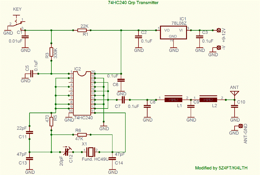
74HC240 Qrp Transmitter.


Description.

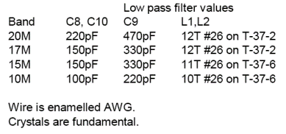
The ARRL HB describes an experimental 0.5W transmitter that uses a 74HC240 octal inverting buffer. One section is used as a fundamental frequency oscillator, four sections are used as an amplifier, while three sections are grounded, and unused. The three unused sections can be put to use in further expansion into a TCVR. Q1 is used to key the transmitter, while the 7808 provides a stable 8V DC supply. THe IC will dissipate heat, and a heat sink should be glued onto it using epoxy. The low pass filter is standard, and the values for some HF bands are given in the table above. This design forms the basis of a minimal QRP TCVR that I am developing, as part of my education in electronics.

http://www.qsl.net/5z4ft/74hc240qrp.html

Saturday, March 19, 2011

Broadband Linear Power amplifier

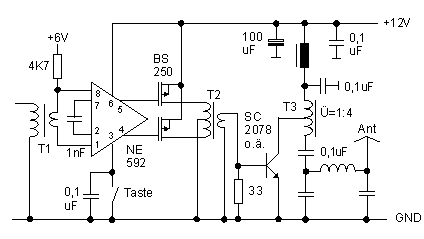
A broadband output transformer in lieu of the parallel tuned circuit is also worth a try. The 10-ohm emitter resistor, capacitor C1 and the 10 uH choke all disappear if FETS are employed. This design probably represents an all-time low in parts count to achieve 1 watt of linear power output, with only 8 components. Note, however, that the 2N3906's actually produce 50% more output for very little added complexity. We could stop at this point, connecting our 1-watt powerhouse to an antenna (via a low pass filter, of course!), or use this circuit to drive an a RF power transistor of more substantial proportions, as shown below. Depending on the frequency, we can achieve 4 to 6 watts output with 0,5 to 0,75 amps current consumption from our 13.8 VDC supply, using a Japanese bipolar device (2SC2078) intended for CB radio and similar applications.

Fig. 2: MOSFET's and RF power transistor

{short description of image}